

| FAQ #206 | |
  |
|
 |
Ignition Coil |
 |
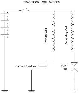
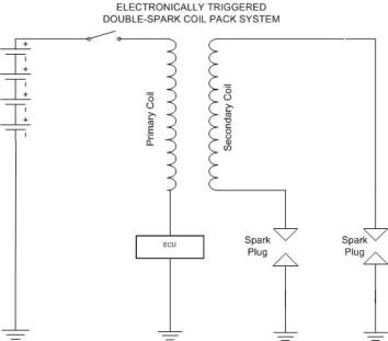
What it does The ignition coil is a high voltage (low current) transformer that converts the vehicle’s 12 volt power supply to the 25-30,000 volts required to jump the gap of the spark plug, thus instigating combustion. How it works:  Since the advent of engine management, ignition coils have undergone a complete redesign. Gone are the tradition oil/asphalt filled, barrel shaped coils, now virtually all manufacturers use resin filled plastic coils which are manufactured in all shapes and sizes. They are smaller, lighter and more efficient but regrettably they are not always more reliable. Since the advent of engine management, ignition coils have undergone a complete redesign. Gone are the tradition oil/asphalt filled, barrel shaped coils, now virtually all manufacturers use resin filled plastic coils which are manufactured in all shapes and sizes. They are smaller, lighter and more efficient but regrettably they are not always more reliable.Although they appear completely different they still rely on Faraday’s laws of electromagnetism to generate this high voltage. For those of us who haven’t been to school in the past few years, here’s what happens; When a voltage is passed through the primary windings (from the battery (+ve), via the ignition switch, through to ground (–ve)) a magnetic field (flux) is generated around the windings. If the voltage is interrupted (switched off) the magnetic field collapses, this generates a voltage in the secondary windings. This generated or induced voltage is dependant upon the ratio of the windings (primary to secondary, the design of the coil and how quickly the voltage is turned on and off. The switch that was used for many years was the ignition contacts. These were mechanically driven by the engine and timed to trigger the ignition just before the piston reached top dead centre. During the late 70’s and early 80’s electronic ignition replaced the mechanically operated contacts. This enabled a faster switching speed (hence higher voltage output) and more accurate ignition timing settings (no mechanical switch to wear/deteriorate). Electronic ignition used a non-contact sensor (hall or inductive type) that was the forerunner to today’s cam/crank sensors. With government legislation dictating the need for ever decreasing mixture strengths and engine manufacturers designing more and more powerful engines, the need arose for higher voltage ignition systems. High in-cylinder pressures, hot combustion chamber temperatures and lean mixture strengths all make it difficult for the spark to jump across the plug gap, thus a higher voltage spark is required. The most demanding applications include turbo/super-charged, lean burn or direct petrol injection applications. Following the advent of electronic ignition, designers turned to developing the ignition coil.  The traditional ignition reached its zenith. It became “saturated” at the higher voltages demanded from them and alternatives were sought. The higher voltages required to trigger the spark also caused under bonnet problems with high tension (HT) lead insulation, both voltage and emission interference. A new design ignition system was called for, say hello to the resin filled plastic coils, say goodbye to distributors and HT leads. The traditional ignition reached its zenith. It became “saturated” at the higher voltages demanded from them and alternatives were sought. The higher voltages required to trigger the spark also caused under bonnet problems with high tension (HT) lead insulation, both voltage and emission interference. A new design ignition system was called for, say hello to the resin filled plastic coils, say goodbye to distributors and HT leads.The development of these coil “packs” has only been made possible with the advent of computer aided design packages (CAD). The coils are designed and tested before manufacture. As are virtually all components on the modern motor vehicle, the designer’s pencil has gone to the same bin as the contact/condenser sets. The coil assembly is now precisely matched to the other ignition system components (plugs, ECU driver stage etc)all of which are integral to the engine management system. The secondary circuit of the coil is now completely isolated from the primary (see diagram B), this allows the use of “double ended” coils with two HT outputs, these are also incorporated into multi cylinder “packs” comprising of an assembly of double ended coils to enable “coil per cylinder” set ups. Also, as resin coils can be made smaller and of any shape they can even be fitted directly on top of the spark plugs (pencil coils). Coil on plug units reduce the electrical capacitance of the HT circuit and reduce the number of HT components by removing the “weak link” the HT lead. This also increases ignition system reliability. They come in all shapes and sizes. Pencil Coils, Block Coils, Cassette Coils. Testing: When testing ignition coils, start with the basics. External checks for sign of HT leaks (tracking), check for cracks to the insulating material, check for corrosion to the terminals. Next move onto testing the internal resistances, check primary and secondary windings, check for the resistance (if any) between the two circuits. Compare the readings to the relevant data manuals. These tests will highlight many faults however; Full testing however is very difficult as the most common failures occur with internal insulation failure. Cracks develop in the resin that insulates the primary from the secondary windings. This causes HT voltage to leak down through to the primary coils. Without specialist equipment it is impossible to test for this. Checking the resistance between the coils with a conventional Ohm meter will simply show an open circuit, it’s only when there is 30,000 volts trying to get out that the faults show. To spell it out, testing the resistance of the primary and secondary windings will not guarantee an ignition coil’s serviceability. Caution, as the coil is now controlled by the ECU any deterioration of the coils internal insulation could result in ECU failure. Ignition coils should always be replaced in sets. All the coils on the vehicle have done the same work, if one has failed then the others will be on their way out, replace just one at your own risk. |
| Views | 3367 (Unique 2043) |
| Member Rating : | Not yet rated |
| FAQ Posted by | C6Dave |
| Info | Created: 07 October 2009 Last Updated: 18 December 2015 |