

| FAQ #200 | |
   |
|
 |
MAP Sensor |
 |
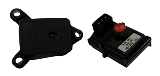
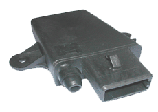
What it does An electronic sensing element converts engine vacuum (or pressure for turbo/supercharged applications) into an electrical reading which the ECU interprets as an engine load signal. As engine load changes, so does the engine’s inlet manifold vacuum, the corresponding signal reflects this. The ECU uses this information to calculate the engine’s ignition/fuel system requirements. How does it work?  Many different types of MAP sensor have been used throughout the development of EMS. The most common device in use today consists of a silicon chip (surprise, surprise) into which a small diaphragm has been etched. Small electro-deformation resistors measure any deflection of this diaphragm; internal circuitry amplifies this signal and sends the ECU the correct message. Many different types of MAP sensor have been used throughout the development of EMS. The most common device in use today consists of a silicon chip (surprise, surprise) into which a small diaphragm has been etched. Small electro-deformation resistors measure any deflection of this diaphragm; internal circuitry amplifies this signal and sends the ECU the correct message.Two different types of output have been used, linear or digital. Linear types have a voltage that rises or falls in line with manifold pressure/vacuum. Digital types have a sine wave output which the frequency changes in line with manifold pressure/vacuum. It is now quite common to have a temperature sensor built into the pressure sensor. This gives a separate output to enable the ECU to calculate air/fuel density. Traditionally MAP sensors were mounted under the bonnet, often on the bulkhead. Modern versions are located on the inlet manifold and due to their reduced size are often overlooked. Reasons for failure/testing: As with other sensors, the component itself will have a very long service life in ideal conditions, it’s when it’s fitted under the bonnet of a motor vehicle in real world conditions that things start to go wrong.  operate on low voltages (0-5v) and low output signals; even the slightest wiring or poor connection fault will cause an error. A short to 12 volts is also quite a common problem caused by a wiring loom or fuse box fault. Check the supply voltage and compare with known data. A short to 12v will generally affect all of the other engine-mounted 5 volt sensors and damage may result. Ensure that the wiring and power supply is checked before you renew the sensor to prevent damage to the replacement sensor. operate on low voltages (0-5v) and low output signals; even the slightest wiring or poor connection fault will cause an error. A short to 12 volts is also quite a common problem caused by a wiring loom or fuse box fault. Check the supply voltage and compare with known data. A short to 12v will generally affect all of the other engine-mounted 5 volt sensors and damage may result. Ensure that the wiring and power supply is checked before you renew the sensor to prevent damage to the replacement sensor.Check the output signals as close, electrically, to the ECU as possible, (this ensures that the wires and connectors are in good order) note the vacuum and output readings and compare them to a known data source. The vacuum source is from the inlet manifold via a small pipe, this often allows oil into the sensor, which will cause its failure. Some manufacturers use an in-line oil trap to prevent this from happening; this trap can get blocked and will cause similar symptoms to a failed sensor. Note: Ensure that the correct sensor is used as they are easily damaged. |
| Views | 3632 (Unique 2305) |
| Member Rating : |           10.0 - 1 vote 10.0 - 1 vote |
| FAQ Posted by | C6Dave |
| Info | Created: 07 October 2009 Last Updated: 18 December 2015 |