| C6owners :: Forums :: C6 Support :: Super Sticky |
<< Previous thread | Next thread >>
|
Level Switch for Coolant Reservoir / Degassing Tank |
    Please Register to enjoy additional Member Benefits |
| Author | Post | ||
David Hallworth
 
|
|
||
    Member No: #90
Location: Glasgow |
Just to add to this, I was messing around with the Lexia today after clearing a handbrake fault and when I was messing around in the BSI menus I found this...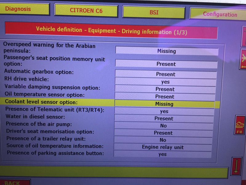 Does that mean that the ECU can support a dedicated coolant level sensor? If so, I wonder if we can find out what pins of the ECU the coolant sensor would be wired into for this feature to be enabled? If it can be done that way rather then piggy backing the oil pressure it'd be handy. David. |
||
|
|
|
||
|
e3steve
|
|
||
  Member No: #1163
Location: Warsash, Hants & Palma de Mallorca, Spain |
Tjensen wrote ... We must learn form your problems: What is causing clogging and dirt to gather in the air distribution system ? In the simple old times, that would have been backfiring or in the not-so-old times leaks and problems in the engine crankase ventilation system, allowing oil deposits into the system. It should have been nice and clean. - Click Here - |
||
|
|
|
||
eke

|
|
||
|
Member No: #624
Location: Oulu |
Hello gmerry, I see you are again posting to Forum Is it possible for you to provide some more information on how to connect the level sensor wires to car systems ? Do you have any pictures from connections in your car, it would be very helpful. Thanks anyway Eke |
||
|
|
|
||
|
ChrisW
|
|
||
 Member No: #1335
Location: Surrey |
At 14 years old, with a Chemical Metal bodge (successful – separate thread) on the corroded pipe behind the NSF wheel arch and having read the horror stories about the splitting thermostat housing, I thought I should fit a level warning device on the coolant tank on my C6. Gmerry’s suggestion to connect a float switch to the oil pressure sensor is very clever. But I don’t like float switches, especially on an application like this when the float will always be in the up position, perhaps for years, before there is a leak and the level drops. Crud and slime will inevitably build up on the stem and stiction will prevent the float from falling. There is a high risk that the switch will fail dangerous. I fitted an electronic level control device from ebay (cost about £6 delivered from China). It is based on sensing the conductivity between 2 probes and triggering when one of the probes is exposed because the level has dropped. I had a similar one on my garden pond for many years and it was totally reliable. I drilled two 5.5mm holes in the top of the tank. I took two 1” lengths of 6mm brass studding and soldered a 6mm brass nut on each one leaving enough thread protruding to take another nut in order to connect the wires to the unit. To make the probes, I then drilled a short 1mm hole into the end of each, soldered 2.5mm T&E wire into the holes, cut the wires to length (one to the bottom of the tank and one 30mm shorter). I screwed them into the holes in the tank with an O-ring to seal. I stripped all the insulation from the probe wires to maximise the area for conduction. First, though, test the control unit using a cup of water to check the right terminals to use. Run a wire from the oil pressure sensor to the control unit so that the solenoid switch closes to the car earth at low level and opens when the top probe is immersed in coolant. With the engine running the oil pressure warning comes on when the connection to the ECU switches to earth either through the oil sensor or the level control device. I fitted a test-switch between the top probe and the control unit to simulate the probe being exposed and opening the switch with the engine running triggers the oil level STOP warning. I had not recognised that glycol mixtures are not as good an electrical conductor as water and the excess resistance caused erratic operation. I solved this problem by wiring a 65,000 Ohm resistor across the probe-terminals in the control unit. The number isn’t critical. It should be low enough that the warning isn’t triggered when the reservoir is full but high enough to trigger when it is empty. Perhaps better would have been to place the probes about 2cm apart, not about 6cm as I did, which would remove the need for the resistor. The device needs a 12V feed, switched when the ignition is on, which is easy to feed from the main fusebox, run through a separate 1A fuse. It’s a nice easy job with easy access to everything and will give enough warning of a leak to pull over and check things well before any engine overheating. I now have a bottle of Radweld and a couple of litres of water in the boot just in case. I’ve just driven to Cornwall and back with no issues and no worries about coolant leaks. |
||
|
|
|
||
cruiserphil

|
|
||
 Member No: #38
Location: Celbridge |
Hello ChrisW, Well done on your mod. Did you see the retrofit of the original sensor and reactivation of the low coolant warning on the central display posted by member Vaho a few years ago? - Click Here - Best regards, Phil C. |
||
|
|
|
||
|
ChrisW
|
|
||
|
Member No: #1335
Location: Surrey |
Thanks, Phil. I'm afraid I missed Vaho's posting and would have tried to track down the original Citroen sensor had I seen it. My "sensor" and the original appear to work on the same conductivity principle and both will do the job. If I were to do the job again and the original sensor was no longer available, I would drill the holes in the tank about 1 cm apart to mimic the spacing in the original. I think the main thing is to have a sensor, ideally the original, in the tank because it is an easy and low cost way of avoiding a potential disaster with our ageing C6's. Chris |
||
|
|
|
||
|
cruiserphil
|
|
||
|
Member No: #38
Location: Celbridge |
Hello ChrisW, Well done on your own installation. Totally agree with the security it brings. I have the VAHO mod installed on our 2.7 and it already alerted me to coolant loss due to the failure of the inlet cooling tank. Would it be possible for you to put together an "instruction" on your modification. The reason I ask is that it would be a proven solution for 3.0HDi owners. The VAHO mod. can't be completed on the 3.0HDi as the BSI alarm menu does not have the "Low Coolant Level" alarm function for the central display available to activate. Hope you'll consider, as I for one will fit it! Best regards, Phil C. |
||
|
|
|
||
|
ChrisW
|
|
||
|
Member No: #1335
Location: Surrey |
I am just about to go on holiday and will do this when I get back. Does the 3.0 have a plastic tank to drill into like that on the 2.7? And does it have the wire from the oil pressure sensor as in Gmerry's posting? I will get the details of the device from China. I looked for the Cartier float switch but all I could find was expensive watches and jewellery! Chris |
||
|
|
|
||
|
cruiserphil
|
|
||
|
Member No: #38
Location: Celbridge |
Hello ChrisW, It has the same tank. I'll check on the wire I'd say it does. I have a Cartier switch. Wonder would it work with your control box? Enjoy the holidays, Best regards, Phil C. |
||
|
|
|
||
|
ChrisW
|
|
||
|
Member No: #1335
Location: Surrey |
Hi Phil Very good holiday, thank you. Having looked at Gmerry's circuit diagram for the Cartier, above, I don't think it will work with my control box. The Cartier has some electronics inside that generates a 0 or 5V output depending on the level and this is designed to interface with the ECU for the 2.7 engine. The input to my control box is simply the resistance between the 2 probes. When this is too high the box interprets this as one of the probes being no longer immersed in the liquid, which closes the relay so that the wire to the oil pressure sensor switches to earth, which mimics a low oil pressure signal to the ECU. If you want to use the Cartier, it looks like you need to link it to a 5V micro-relay as per Gmerry's diagram. As you already have the Cartier, this may be the best option, with the 5V relay switching the oil pressure wire to earth. Hope this helps Chris |
||
|
|
|
||
|
cruiserphil
|
|
||
|
Member No: #38
Location: Celbridge |
Thanks for the reply ChrisW, Will you still consider a write up? Best regards, Phil C. |
||
|
|
|
||
|
ChrisW
|
|
||
|
Member No: #1335
Location: Surrey |
Not a lot to add to my previous post, which should be easy to follow. The only change I would make is to drill the holes in the top of the tank about 2cm apart. to give better conduction and avoid the 60kOhm resistor. If you put "Water Level Control Switch Level Controller Module Portable Simple Conductive" into the ebay uk search page it will bring up the controller at £5.74 incl. postage from China. I've bought lots of electronics from China with no problems. It takes about 3 weeks to arrive. As I said in my post, it's best to check the operation of the switch using 2 probes in a jar of water. I took the 12V supply from a battery charger for this. Then it's a simple wiring job to install. The unit is very small. I put it in one of my wife's little jewellery boxes, bluetac'd to the top of the wheel arch. It's a simple job. Best of luck. |
||
|
|
|
||
 User Colour Key: User Colour Key:Head Administrator, Administrator, C6 owner, Technical Expert, C6 Premier Discount Club |
|
Privacy Policy | Cookie Policy | Site Disclaimer | Contact Details | Warranty | Sitemap | C6 Insurance | Quick Facts | Re Call Info | Downloads | Error Codes
| Site and Graphics created by: C6Dave Forum Icons by Axialis Emotes by Seb | 
|

