| C6owners :: Forums :: C6 Support :: The Garage |
<< Previous thread | Next thread >>
|
Relay location |
    Please Register to enjoy additional Member Benefits |
| Author | Post | ||
COLINJ
 
|
|
||
  Member No: #697
Location: Yardley Birmingham |
Hi, Does anyone knows where the relays are located on the C6. My main screen works intermittently upon unlocking it's lights up and another time it doesn't it might work for a couple of days then it starts to play up again iam thinking it might be a sticky relay. Any thoughts would be well appreciated. Many tax Colinj |
||
|
|
|||
|
e3steve
|
|
||
   Member No: #1163
Location: Warsash, Hants & Palma de Mallorca, Spain |
COLINJ wrote ... I doubt that it's a relay; most functions are controlled via discrete, solid-state devices.Hi, Does anyone knows where the relays are located on the C6. My main screen works intermittently upon unlocking it's lights up and another time it doesn't it might work for a couple of days then it starts to play up again iam thinking it might be a sticky relay. Any thoughts would be well appreciated. Many tax Colinj Check out my post concerning RT3 display 'flashing'... - Click Here - |
||
|
|
|
||
|
C6Dave
|
|
||
  Member No: #1
Location: Northumberland |
 - wiring diagrams are on site: - Click Here - - wiring diagrams are on site: - Click Here -
|
||
|
|
|
||
|
Hovertank
|
|
||
 Member No: #4746
Location: London |
Hello, does anyone have a diagram showing the physical location of all the relays on the car? I've looked at all the electrical diagrams in downloads and it's not there. I mean something like the ECU location diagram. I'm specifically looking for relays 6 and 7 |
||
|
|
|
||
|
MGmike
|
|
||
 Member No: #3151
Location: South Queensferry |
There's relays placed all over the car. Some in the BSM under the bonnet, some on the BSI in the passenger compartment and others near the consumers e.g. fans, suspension pump etc. What do relays 6 & 7 control? |
||
|
|
|
||
LightMatic

|
|
||
|
Member No: #2097
Location: Mostar, Hercegovina |
Hi, I have pdf document. How can I sent it to you? | ||
|
|
|
||
|
Hovertank
|
|
||
|
Member No: #4746
Location: London |
Thanks for the replies. The relays are mentioned in the BHI circuit diagrams, leading to the hydraulic suspension pump and ECU. I found a bunch of relays in the engine compartment fuse box, they are revealed when you take off the plastic grid under all the ECU sockets. They are embedded in epoxy or some kind of hard filler, and are not labelled or shown on a diagram inside the fuse box cover. There is a diagram of that fuse box in the downloads section, but it only shows fuses/master fuses not relays. I'm fairly positive it's one of them, but it's a lot of risk and effort digging them out for testing. |
||
|
|
|
||
|
MGmike
|
|
||
|
Member No: #3151
Location: South Queensferry |
Hovertank wrote ... Thanks for the replies. The relays are mentioned in the BHI circuit diagrams, leading to the hydraulic suspension pump and ECU. I found a bunch of relays in the engine compartment fuse box, they are revealed when you take off the plastic grid under all the ECU sockets. They are embedded in epoxy or some kind of hard filler, and are not labelled or shown on a diagram inside the fuse box cover. There is a diagram of that fuse box in the downloads section, but it only shows fuses/master fuses not relays. I'm fairly positive it's one of them, but it's a lot of risk and effort digging them out for testing. What fault symptoms do you have? Relay 6 is on the BSM in the engine bay and 7 is on the BSI in the passenger compartment. As you say, the engine bay one is sealed and the best way to check it's working will be to check if F14 has power on it. It also feeds the instrument panel and therefore if that's working you're all good there. It's not clear in the wiring diagram what R7 does for the suspension! But, from the fuse numbers it feeds, it appears to feed power to the engine relay unit (BSM), wipers etc. and I guess if the wipers work you should be good on that one! What's not shown on the diagram is fuse G33 located in the top of the glovebox fuse access point above the BSI, this provides power to the BHI. There is also the main motor relay (Item 1704) which is mounted close to the pump above the chassis rail. You'll need the bumper and possibly the headlight out to get access to that one! |
||
|
|
|
||
|
MGmike
|
|
||
|
Member No: #3151
Location: South Queensferry |
COLINJ wrote ... Hi, Does anyone knows where the relays are located on the C6. My main screen works intermittently upon unlocking it's lights up and another time it doesn't it might work for a couple of days then it starts to play up again iam thinking it might be a sticky relay. Any thoughts would be well appreciated. Many tax Colinj Colin, when you say main display do you refer to the speedo or the display in the centre of the dash? |
||
|
|
|
||
|
Hovertank
|
|
||
|
Member No: #4746
Location: London |
Thanks MGMike, sorry for the long delay in replying, I'm pretty busy at the moment. The problem started with the car one morning sitting in low position and not drivable The BHI/Suspension pump is not running. I'm getting the "Suspension Fault" and "55 MPH max" errors on the display. My Diagbox can't communicate with the BHI ECU. Since so many functions run through that ECU it has to be working in some way. If you disconnect it and turn on the ignition the speedo display etc. don't work. The attached image is what I'm using to debug the problem - the terrible annotations are mine. What I've done so far: 1. Checked all the fuses - The maxi 40amp MF4 was blow. I replaced it with a 50amp one. 2. Drained the LDS and removed the BHI unit 3. Replaced the BHI with a used one with the same part number/refilled the LDS. The new BHI has identical pipe and electrical connectors. I gave the pump/motor a good clean and tested the motor off the car. The bearings/windings/brushes are much better than the one that came off. The motor does not have a foil capacitor like the old one. The pump works on the bench and in the car if I supply a small voltage to the single plug connector on the pump. 4. Checked all the wiring/cleaned the connector blocks - voltage and continuity tested them. All looks good, the earths and voltage to the pump are good, the live is getting 14v with the engine running. So everything mechanical and electrical is good. The single wire 7111 from the 7715 BHI ECU is the problem, the ECU is not activating the pump. I don't have a clue why that is, given that most of the ECU functions seem to be working, it must be a piece of logic/rule in the ECU not being triggered. It may be the "static pressure sensor" (part 5273.A2 9651503880) visible in the drivers wing screwed into one of the suspension metal tubes, it seems to tell the ECU what the LDS pressure is. If that's open circuit/broken then maybe it's the cause. There were faults for it a while ago in diagbox. I think it's in the diagram on wire 9001R going to "77--" but maybe I'm wrong. Does anyone know the Lexia/Digabox steps to program a new BHI to the car? It's mentioned in some of the documents in the downloads section, but there are no instructions. 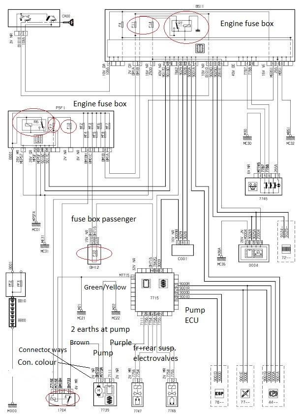
|
||
|
|
|
||
|
MGmike
|
|
||
|
Member No: #3151
Location: South Queensferry |
Hovertank wrote ... Thanks MGMike, sorry for the long delay in replying, I'm pretty busy at the moment. No worries life is like that! Hovertank wrote ... If you disconnect it and turn on the ignition the speedo display etc. don't work. yep, that's because the BHI is attached to the CANBUS and disconnecting it upsets the CAN Hovertank wrote ... The attached image is what I'm using to debug the problem - the terrible annotations are mine. What I've done so far: 1. Checked all the fuses - The maxi 40amp MF4 was blow. I replaced it with a 50amp one. 2. Drained the LDS and removed the BHI unit 3. Replaced the BHI with a used one with the same part number/refilled the LDS. The new BHI has identical pipe and electrical connectors. I gave the pump/motor a good clean and tested the motor off the car. The bearings/windings/brushes are much better than the one that came off. The motor does not have a foil capacitor like the old one. The pump works on the bench and in the car if I supply a small voltage to the single plug connector on the pump. 4. Checked all the wiring/cleaned the connector blocks - voltage and continuity tested them. All looks good, the earths and voltage to the pump are good, the live is getting 14v with the engine running. So everything mechanical and electrical is good. The single wire 7111 from the 7715 BHI ECU is the problem, the ECU is not activating the pump. I don't have a clue why that is, given that most of the ECU functions seem to be working, it must be a piece of logic/rule in the ECU not being triggered. It may be the "static pressure sensor" (part 5273.A2 9651503880) visible in the drivers wing screwed into one of the suspension metal tubes, it seems to tell the ECU what the LDS pressure is. If that's open circuit/broken then maybe it's the cause. There were faults for it a while ago in diagbox. I think it's in the diagram on wire 9001R going to "77--" but maybe I'm wrong. Does anyone know the Lexia/Digabox steps to program a new BHI to the car? It's mentioned in some of the documents in the downloads section, but there are no instructions. I would fit the original ECU on top of the new motor to ensure you have compatibility. The BHI doesn't need programming to the car other than checking/correcting the heights. Are you sure F33 in the glovebox is good and there's power on pin H4? The static pressure senor fault is a red herring. I have two with sensor faults that work fine. I'm guessing it goes into a default mode when the sensor reports a problem. What voltage do you have on cable 7111 and does it change when you expect the pump to start e.g. when you press the unlock on the key? |
||
|
|
|
||
|
Hovertank
|
|
||
|
Member No: #4746
Location: London |
Thanks for that, I should have said - I did try the original ECU, it was unreachable by Diagbox before and after I replaced the maxi fuse. I tried it on its own after the "new" ECU as well by switching the 32 pin block connector to it. All fuses are good for continuity, F14 has 12+ volts. I will check F33 for voltage as well, I think it's the main power for the ECU (from MF3) so parking brake/ESP etc. would be erroring if it was blown. I'm just using a 9v battery with crocodile clips to trigger the pump via 7111, so that's 9v negative to earth, 9v positive to the 7111 terminal on the relay box clamped to the side of the pump. It's a part discharged rechargeable 9v battery with only about 6v output. The output from the ECU on the 7111 line at the pump terminal plug is just a few millivolts, it seems to vary all the time. I checked the continuity from the 7111 pin in the 32 pin block to the pump terminal wire and it's good. I will report back on H4 tomorrow. |
||
|
|
|
||
|
MGmike
|
|
||
|
Member No: #3151
Location: South Queensferry |
Hovertank wrote ... I will check F33 for voltage as well, I think it's the main power for the ECU (from MF3) so parking brake/ESP etc. would be erroring if it was blown. F33 is noted as G33 in the owners manual and only feeds power to the BHI ECU. F14 feeds the things you mentioned and the power relay for the BHI motor. It has no connection to the ECU. It must be okay if you can trigger the motor on by using the 9v battery. |
||
|
|
|
||
|
onthecut
|
|
||
 Member No: #2793
Location: West Mids |
I'm probably missing something here, but is it perhaps the case that the motor has simply died ? I think a real problem wih many of the diagnostics is that the fault you are trying to arrive at triggers a whole load of connected warnings which only confuses matters. Also, depending on the diagnostic kit, the readings can be of very variable accuracy. If you haven't already, I'd pop it out and have a look at the brushes. Mine had complately eaten one of the brushes. Mike. |
||
|
|
|
||
|
MGmike
|
|
||
|
Member No: #3151
Location: South Queensferry |
Mike, you missed the bit where the BHI was replaced and motor that was bench tested before install. Also, it can be forced to run by applying a voltage to the "trigger" wire from the ECU. |
||
|
|
|
||
Go to page >>
|
|
 User Colour Key: User Colour Key:Head Administrator, Administrator, C6 owner, Technical Expert, C6 Premier Discount Club |
|
Privacy Policy | Cookie Policy | Site Disclaimer | Contact Details | Warranty | Sitemap | C6 Insurance | Quick Facts | Re Call Info | Downloads | Error Codes
| Site and Graphics created by: C6Dave Forum Icons by Axialis Emotes by Seb | 
|


