

| FAQ #232 | |
   |
|
 |
CAN BUS |
 |
CAN stands for Control Area Network. It is a form of multiplexed wiring designed by Bosch and allows the linking of a number of control systems together, normally in a vehicle, so that they can share information. In the past it would have been necessary to have at least one wire for every signal on a vehicle making wiring looms bulky and expensive. CAN bus multiplexing allows a large number of signals to be transferred digitally using only a pair of twisted wires. Sharing of information on a CAN bus also reduces the number of sensors that are needed. For example the engine controller has its own sensor to monitor coolant temperature. Using CAN it can share the temperature reading so that the information is available to any other systems on the car that are interested. One such system might be the instrument cluster, which would use the information to drive its temperature gauge. CAN bus has been used in road cars for over 10 years. Starting at first with the high-end prestige vehicles, it is now commonplace in virtually all European cars and is becoming more popular in the US and Japan. While CAN bus is a very efficient way of connecting control units in a vehicle, it does present a problem to anyone fitting aftermarket equipment to a vehicle. This is because signals such as vehicle speed or RPM that used to be sent on separate wires can no longer be ‘tapped’ into directly. 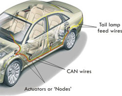 The idea behind CAN is simple. The idea behind CAN is simple. Instead of connecting everything to a central control unit through a main wiring harness, each component in the network has its own processing and communication capabilities, with one data channel connecting all units. In automotive CAN applications, the instrument panel, power windows, body accessories and even many sensors and actuators all have their own individual mini-control unit. All the units, called ‘nodes’, communicate with each other through a single pair of wires. These are twisted together to ensure minimum interference and is known as the ‘data bus’. All the data on the bus is addressed to a specific node or group of nodes by function, not location. The relevant nodes respond to a particular pre-programmed protocol. For example, the vehicle speed sensor will put its data on the bus, and every other control unit that needs vehicle speed information will receive it directly without having to go to the PCM (Pulse Code Modulator ) for a VSS ( Vehicle Speed Sensor ) signal. Because there are multiple nodes sharing a single bus, every date package includes a priority code. This will ensure, for instance, that if the ABS control unit and the lighting unit both send a message to the PCM, the critical ABS system message gets to go first. CAN technology will significantly reduce the number of connector pins and wires in the vehicle. With extra ‘blank’ connectors built into the network loop, or with a splice kit for adding connectors, nodes can be added on the production line (or even aftermarket) without running a new wiring harness. However, designers have built in more than one network on the vehicle, linked by ‘gateways’ where appropriate. The mission-critical nodes will be linked on a high-speed Class C network that can operate in virtual real-time. Less critical items, such as the instrument panel, lighting systems will use a slower Class B network, and ‘occasionally used’ body accessories, such as power windows are likely to use a Class A network. *Activated driver assistance systems inform the driver about all relevant data being transferred around the vehicle - the corresponding display is then activated either in the instrument display or on a centre panel display. Computers for engine and transmission control or for lighting system management monitor the vehicle using the data transmitted via the CAN bus. The systems no longer operate in isolation alongside one another, but can now quickly react to the information from one another. The CAN bus is an optimal solution for managing all vehicle electrical and electronic functions. As a result, effective fault monitoring and diagnosis of the systems are integrated into the CAN bus, defects can be localized more quickly and even temporarily compensated for by corresponding secondary systems. For example, a faulty tail light function can be temporarily replaced by a brake light bulb. The driver would instantly be informed of the failure in order to address the problem. *Activated driver assistance system is hugely relevant for the towing customer. Particular features such as TSP (Trailer stability program) now being introduced and currently installed in nearly ALL new VAG vehicles, BMW X series and the newly produced GM vehicles. The alarming thing about these systems, are that they are a incredibly easy feature to install and activate when towing. With a change to the existing ESP, ( Electronic Stability Program) the vehicle is able to correct a ‘snake’ in a trailer or caravan. These systems are dormant in the software of the vehicle and brought into operation when the car detects a trailer connected. How does the vehicle know a trailer is connected? This happens in a number of ways but the most common method is a signal generated by the towing module, which is recognised by the central computer. The signal is sent when a tow plug is inserted into the socket. Trailer Detection can also activate other features associated with towing. For systems such as TSP to operate it is essential to have a towbar wiring kit installation which communicates directly on the CAN bus. These WILL NOT function if a by-pass wiring system is installed. Trailer Detection. This is simply an element of a CAN protocol which is activated usually by the car acknowledging a trailer is connected. This is not done by any mechanical means, but by simply inserting the trailer plug into the towing socket. The car realises it has a trailer connected and now stimulates certain operating systems to wake up. These systems include: Trailer Stability Programs A change to the parameters of the vehicle’s Electronic Stability System - the car detects the ‘Snaking’ of a Trailer and by activating the ESP sensors in the vehicle, It brings the caravan back under control. C2 Function The C2 function of the trailer is activated, usually by a Double frequency flash rate of the car indicators, should a trailer indicator fault be detected. Fog lamp cut-off The rear fog lamp on the car is switched off when towing if a fog lamp is fitted to the trailer. PDC Cut-off If the vehicle is equipped with parking sensors these will be automatically turned off when a trailer is connected. The important features of these operations is that they DO NOT function if the car is fitted with by-pass technology used in towing electrics. They will only work when they detect a towing module which is sending and receiving signals through the CAN bus system. With such advances in vehicle technology, manufacturers have sought to develop a particular system which gives them the edge over their competitors. This is most apparent in on-board vehicle safety systems. In the 1980's, we saw ABS become a selling feature for one or two manufacturers, this is now common place on 99% of vehicles on our roads. Over the last few years we have seen other safety features such as Brake Force Distribution, Side Impact Bars, Rear Passenger Airbags, Curtain Airbags and so on. The latest safety feature which is fast becoming a primary safety feature on virtually all new vehicles is the Electronic Stability Programme (ESP). This comes in various guises depending on the manufacturer. For Example, BMW call this DSC (Dynamic Stability Control), Toyota use the term VSC (Vehicle Stability Control). Advances in vehicle technology have enabled a number of other safety features to incorporate a traile How does ESP function? The electronic stability program (ESP) is a further enhancement to the Anti-Lock Braking System (ABS) and Traction Control System (TCS). The ESP is designed to detect a difference between the drivers control inputs and the actual response of the vehicle. When differences are detected, the system intervenes by providing braking forces to the appropriate wheels to correct the path of the vehicle. This automatic reaction is engineered for improved vehicle stability, particularly during severe cornering and on low-friction road surfaces, by helping to reduce over-steering and under-steering. To implement ESP functionality, sensors must be added to the ABS system. A steering wheel angle sensor is used to detect driver input, with a yaw rate sensor and a low-G sensor that measure the vehicles response. Some ESP systems include a connection to the powertrain controller of the vehicle to enable reductions in engine torque when required. How does TSP function? When trailers or caravans start to sway dangerously, it is usually a result of the way of driving, speed, crosswinds, road condition and/or, a badly laden trailer or caravan. Caravans and horse box trailers present a special risk. When "snaking" occurs, many drivers display the wrong reaction and under stress, try to keep their tow vehicle and trailer on track by counter steering. This will only amplify the swaying effect and eventually result in an accident. The specific additional function of ESP, known as the Trailer Stability Program (TSP), recognizes swaying on the basis of the typical yaw rate in the tow vehicle. This allows for the right measures to be initiated at an early stage: the towing combination is slowed down to a non-critical speed by automatically braking all 4 wheels of the towing vehicle individually, whilst simultaneously reducing the engine speed and thus correcting the swaying movement. In most cases, providing the vehicle has been equipped a "Vehicle Specific Towbar Wiring Kit", the additional software in the ESP module is activated as soon as the electrical connection cable of the trailer is plugged into the towbar socket. How do I know if TSP is working? When the vehicle detects a swaying motion caused by a "Snaking" trailer, the TSP system will start to correct the movement. The driver will be informed via a flashing ESP light on the instrument display. Note: Some vehicles equipped with this system will perform a firm braking action. It is recommended that whenever the TSP is correcting the trailer that the steering wheel is kept in a straight position, in order for the towing combination to be controlled. Source: Trailer Connections BigJohnD wrote ... It's about risk and preventative and post-incident actions. The presence of ESP and auto-activation of TSP when hooking up a trailer/caravan to monitor things like: differences in tyre circumference, steering wheel angle, battery voltage, temperatue, clutch pedal sensor (for manuals), accelerator pedal position, engine speed, gearbox information, vehicle speed, Longitudinal acceleration, Lateral acceleration, roll angle, yaw, wheel speed sensors, electro-valve senors, brake fluid level, brake pressure and even the status of the handbrake. is the preventative part. The implementation of the system to stabilise the car's travel is post-incident part. To have all those inputs activating a system which responds as if no trailer is attached when there is, is too big a risk and could well be construed as contributory negligence by insurers, expert witnesses and courts. Most people seem to equate adding a tow bar to making sure the rear lights work. It's often forgotten than the whole dynamic of the forward motion is significantly altered. Citroën have gone to great lengths to ensure everyone's safety by incorporating a sophisticated vehicle stability management feature to reduce the risk of unwanted incidents. Dedicated Wiring: Citroen 2004+ Dedicated towbar wiring systems are manufactured for specific vehicles and are non-interchangable between models. Developed to perfectly integrate into the vehicle’s existing systems to allow usage of inbuilt safety features and preserve the integrity of multiplexed or CAN-Bus circuitry. * Complete wiring system * Pre-assembled loom * No guesswork or hunting for wires * Neat Installation – no more wiring “bird nests” * Preserves the integrity of vehicle systems * Compatible with manufacturers’ Towing Stability Programs* * A professional installation – straight from the box * Manufacturer’s Technical Support provided What are the advantages of Dedicated Wiring Systems? Do I need a Dedicated Kit? It is currently not a necessity to install a dedicated wiring kit, as relay technology kits are available which add towing electrics without disturbing modern vehicles’ complex systems. However there are an ever-increasing number of serious advantages to installing a fully dedicated and integrated towing electric system. As opposed to the traditional, relay technology wiring kits which aim to completely bypass vehicle systems, The read/write function of the CAN-Bus wiring kits means that inbuilt vehicle systems such as Rear Foglamp Cut-off, Parking Sensor Cut-off and – more importantly, manufacturers’ Towing Stability Programs can be used. Towing Stability Programs? Modern vehicles are packed with intelligent safety features – and towcars have not been forgotten. Vehicle Systems may include features for towcars to increase stability and safety whilst towing – or to adapt safety systems to account for added load and different handling whilst towing such as: * Interactive /Self Levelling Suspension * Crash Anticipation * Hill Start Assist * Intelligent Braking * Electronic Stabilisation Program (ESP) * Fog Lamp Cut Off * Parking Sensor Cut Off Some of these features are, or can be, programmed to perform differently where the presence of a trailer or caravan is detected, to adapt to the different handling caused by towing.* The traditional Relay Technology Bypass Systems are unable to activate these systems. Please note that the above is a general overview of systems available at the time of writing, and is neither an exhaustive list of systems continually in development, nor should it be taken that every vehicle has some or all of these systems. How are they Installed? Because each kit is dedicated to specific vehicles, installation naturally varies. Where kits plug into the vehicle loom, for example, to manufacturers’ existing sockets, a matching plug is used for a simple and non-invasive connection. On CAN-Bus systems without existing provision for straight connection, such as VAG group vehicles, the installation is typically made by feeding the pre-assembled loom into the vehicle and plugging the loom to the CAN-Bus module included with the kit (this might sound complicated, however - to the installer this is simply a case of slotting the plug into the black box). The towing electrics loom is then fed to the fusebox, a fuseholder and fuse inserted into the correct slot in the fuseboard (full instructions provided with each kit). The two twisted control wires are then connected with a splice connector block to the two CAN-Bus signal wires under the dash (again, full instructions are provided). Note: Vehicles can and do vary in installation and the preceding text is a simple illustration of a typical fitting procedure and not a full instruction Source: Towsure |
| Views | 4827 (Unique 2959) |
| Member Rating : |   8.5 - 2 votes 8.5 - 2 votes |
| FAQ Posted by | BigJohnD |
| Info | Created: 27 August 2010 Last Updated: 18 December 2015 |
 Posted by Krtcho Posted by Krtcho Posted by Candide Posted by Krtcho Posted by Krtcho
Privacy Policy | Cookie Policy | Site Disclaimer | Contact Details | Sitemap | Quick Facts | Re Call Info | Downloads | Error Codes
| Site and Graphics created by: C6Dave Forum Icons by Axialis Emotes by Seb | 
|
